
Does size really matter? – Design effect of crystal downsizing
Posted: 16th January 2023
 Miniaturisation is an ongoing trend in the electronic industry. Wearables, smart home devices, mobile devices, electronics in automotive applications... - these are just a few examples of applications that require more and more smaller components. Every manufacturer of electronic components is working to bring smaller and smaller components onto the market. But this size reduction can cause different issues during the design-in process. To help cope with some of these issues this blog is going to focus on the effect on the design when downsizing quartz crystals.
First of all it can be said that the smaller the size of a crystal, the higher the resonance frequency. For quartz, the relationship between the thickness of the quartz blank and the resonance frequency is inversely proportional. This means that when the blank gets thinner the frequency increases. Conversely, this means that a thicker blank is needed to obtain a lower frequency. Since smaller packages are also thinner, it is physically no longer possible to offer frequencies below 16 MHz in the 2.0 x 1.6 mm package or below 24 MHz in the 1.6 x 1.2 mm package. This needs to be taken into account when switching from a larger to a smaller size.
Another feature of smaller crystals is that the Equivalent Series Resistance (ESR) is higher. The ESR of a crystal depends on several parameters such as frequency, crystal size, electrode size and mounting structure. But as a general rule, the smaller the crystal the higher the ESR. During the design-in evaluation the ESR needs to be considered in order to ensure that a stable oscillation can be guaranteed. A stable oscillation is characterized by a safety factor of 5 or more. The safety factor, often also called negative resistance ratio, is defined by the ratio of the negative resistance to the ESR. The formula for the safety factor can be found in formula (1).

The negative resistance in the circuit can be measured by adding a potentiometer in series with the crystal as shown in Picture 1. The resistance of the potentiometer needs to be increased until the crystal stops oscillating - this resistance value marking RADDmax. With RADDmax and the max ESR of the crystal the negative resistance and the safety factor can be calculated.
If the ESR increases, the safety factor decreases. As a result of this a safe oscillation of the crystal cannot be guaranteed anymore (SF ‹ 5). This is in fact something that can happen quite easily if a smaller crystal is used to replace a larger crystal in an older design.
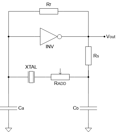
Picture 1: Circuit diagram with RADD
But what can be done to improve the safety factor and guarantee a stable oscillation in such cases? The easiest way to improve the negative resistance and thus the safety factor is to lower Ca and Cb. When lowering Ca and Cb it will cause RADD to be higher at the point where the oscillation stops. This results in an improvement of the negative resistance and increased safety factor. This is why smaller crystals are usually sold with lower load capacitances. So when considering a change from a larger crystal to a smaller crystal one should keep in mind that it requires a change of capacitors as well.
Something else that needs to be considered when lowering Ca and Cb is the trim. In one of the latest blogs we already talked about the load capacitance and the trim in general. Normally it can be said that the trim is higher for larger crystals due to dimension of the blank and the electrode. Furthermore, the trim increases when lowering the load capacitance in a circuit. Now when redesigning a circuit with a smaller crystal, it could be expected that the trim is less, and therefore the frequency is more stable. But as learned in the section above, the load capacitance needs to be reduced in the circuit to maintain the negative resistance and safety factor and thus the trim will increase. So overall the trim will stay the same or even increase when replacing a larger crystal by a smaller crystal. Consequently, an important step during the design-in of a small crystal is to choose the right capacitors for Ca and Cb and to evaluate the right load capacitance in the circuit. Only this can guarantee that the crystal will oscillate within its specifications.
Find out more on our YouTube channel in our presentation "Quartz Crystal Downsizing - Does Size Really Matter?"
For support during the design process please contact our applications support team.