
Myths around load capacitance – how to choose the right capacitors
Posted: 3rd August 2020
The load capacitance in the oscillation circuit is one of the most important values for guaranteeing the precision of a quartz crystal. Nevertheless, at the same time it is one of the most common causes of error during the design of an oscillation circuit. There are a number of misconceptions about load capacitance, which we want to clarify today. In addition to that, we will show you how to choose the right capacitors for your circuit.
Most quartz crystals are used in a Pierce oscillation circuit (Figure 1). Therefore, two external capacitors are needed. Now the question may arise, how to choose the correct values for those two capacitors?
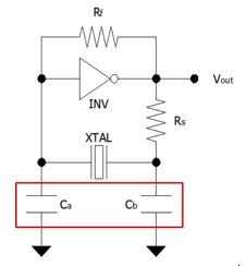
Figure 1: Pierce Oscillator Circuit
The first common misconception is that the load capacitance on the crystal datasheet directly identifies the required values for the two capacitors. This means that if the load capacitance of a crystal is 20 pF, both capacitors would need to be 20 pF. However, this is not correct and this would cause frequency shifts.
Another misconception is that the load capacitance on the crystal datasheet needs to be equal to the sum of both capacitors. If we use the same example with a 20 pF crystal, this means that both capacitors would need to be 10 pF each. However, this is also not correct. You could have been lucky with your circuit and everything could have worked properly until now. In most of the cases, the crystal will work in the circuit even with the wrong load capacitance, however the frequency will shift and this could cause other issues. Because both above‑mentioned assumptions about the load capacitance are wrong, we will now show you the right way:
For the total load capacitance in the circuit, all capacitances need to be considered. Therefore, not only the two capacitors, but also the input and output capacitance of the microcontroller and all stray capacitances must be taken into account. This all together forms the load capacitance. The biggest problem now is that it is impossible to know or determine the stray capacitance without an actual circuit. Therefore, during the PCB Design you have to just guess the stray capacitance and later recheck with the final circuit if the frequency is within the tolerance. Working in the industry for several decades, we experienced that the typical stray capacitance in Pierce oscillation circuit is between 3 pF to 7 pF. With this in mind you can easily determine the values for the two external capacitors Ca and Cb with this formula:
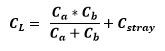
Formula 1: Load Capacitance
Another recommendation is to select Ca and Cb to have similar values, or at least not far away from each other. This will prevent unexpected frequency shifts and other interference. If Ca and Cb should not be equal, then Ca should be smaller than Cb.
However, because you can only estimate the stray capacitance it is really important to measure the frequency of your actual circuit to recheck if the frequency reaches the required accuracy for your application. In addition, our application support team can help you with any further questions relating to the load capacitance or your circuit design.
In our next blog, we will show you in more detail how big the influence on the frequency can be if you have the wrong load capacitance in your circuit.