
How a few pico farads can ruin your timing accuracy
Posted: 1st September 2020
Quartz crystals are widely used in electronic applications because of their accurate frequency. Thanks to IoT, 5G and Industry 4.0, the demand for highly precise clock frequencies is increasing dramatically. However, by making a few mistakes during the design-in process the entire frequency accuracy of the quartz crystal can be ruined. This blog will focus on the influence of the load capacitance on the frequency of the crystal.
In the last blog, we looked in more detail at the selection of the right capacitors for the crystal. With all the information in mind you may ask yourself, why is all of this so important? After all, we are talking about just a few picofarads. What influence would this have on my application?
Depending on the required timing accuracy in your application, this can be very important. The capacitance of the circuit defines the resonant frequency of the crystal. This means if the capacitance in the circuit changes, the frequency of the crystal changes as well. During the production process, the crystal is calibrated to its specific load capacitance. From this, it follows that with the right load capacitance in the circuit the crystal will oscillate within its tolerance. However, every change to the load capacitance will shift the frequency. This means that in the worst case scenario the crystal will oscillate outside its tolerance.
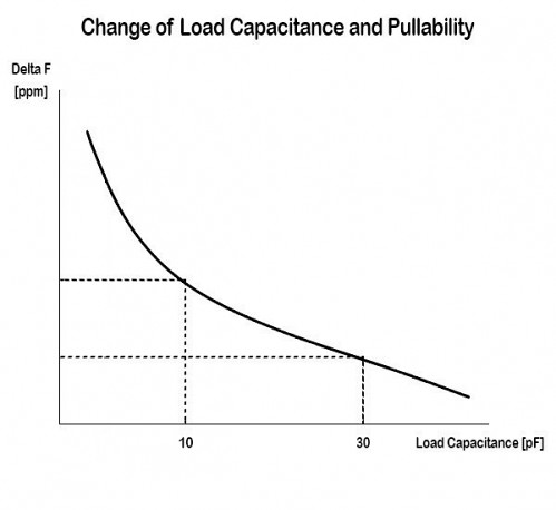
The parameter that identifies how much the frequency of the crystal will shift is the trim sensitivity. This shows by how many ppm the frequency will change, if the load capacitance is changed by 1 pF. The value of the trim can vary from 1 ppm/pF up to 100 ppm/pF and it depends on various factors, such as the size of the blank, the size and shape of the electrode, the frequency, as well as the load capacitance. On one hand, you can say as a rule of thumb, that the bigger the package size the bigger the trim sensitivity. Therefore, the trim of a 1.6 x 1.2 mm crystal will be smaller than the trim of a 7.0 x 5.0 mm crystal. On the other hand, you need to keep in mind that the lower the load capacitance, the higher the trim will be. Consequently, if you have a crystal with 10 pF load capacitance and a crystal with 20 pF load capacitance, the trim of the 10 pF crystal will be higher. In the picture below (Figure 1), you can see how the trim varies with the load capacitance.
Therefore, if the load capacitance in the circuit differs from the specified load of the crystal, the frequency will shift. In addition, depending on the specified load capacitance and the difference between the load in the circuit and the specified load, the frequency change can be dramatic. In the worst-case scenario, the frequency will be outside of the specification and it may not work in your application. This is why it is so important to look at the load capacitance in more detail during your design process.
For support during your design process or if you want to know the trim sensitivity for a specific crystal, please contact our applications support team.